(An ISO 9001:2015; Certified Company & NABL Accredited lab as per ISO/IEC 17025:2017)

SAS Ground Engineers LLP (formerly known as SAS Ground Engineers)

experience to be trusted

Ground Improvment Contracting

Consolidation using

Prefabricated vertical drains

Wick drains, also known as Prefabricated Vertical Drains (PVDs), are plastic strips wrapped in geotextile fabric with molded channels, designed to accelerate the removal of pore water from soft, saturated soils like silts, clays, and peat. This speeds up soil consolidation from years to months, making it suitable for construction schedules.
PVDs consist of a polypropylene core with grooves that allow water to flow freely, wrapped in a filter fabric to prevent soil clogging. These drains are installed via a hollow mandrel mounted on an excavator or crane and driven into the ground to the desired depth. Once the mandrel is removed, the drain remains in place, creating short drainage paths that accelerate soil consolidation. Post-installation and consolidation period, field quality assurance can be done by conducting SPT/CPT, complimented by geophysical non-destructive test methods to ascertain the improved density and shear wave velocity parameters of the ground.
PVDs are commonly used in infrastructure projects (roads, railways, airports), land reclamation, mining (tailing ponds), construction (preparing green and brownfield sites), and flood protection (stabilizing dikes and embankments). They help speed up drainage and reduce long-term settlement, enabling faster and safer construction.
  • Quick installation

  • Accelerated drainage, shortening construction timelines

  • Improved quality control through automated monitoring

  • Effective in deep, challenging soil conditions

  • Cost-effective

    PVDs are particularly useful in low-permeability soils like clay, which normally take years to drain, and are designed to perform even under heavy settlement or deformation conditions.

Compaction using

dynamic compaction

Dynamic compaction is a ground improvement technique where a heavy weight (typically 10-30 tonnes) is dropped from a height in a pre-determined grid pattern to densify loose, granular soils. This process increases soil bearing capacity, reduces settlement, mitigates liquefaction risks, and lowers the potential for sinkholes.
A steel or concrete weight is repeatedly dropped onto the ground from heights of up to 25 meters, creating vibrations that rearrange soil particles and increase density. The number of drops, grid pattern, and phases are tailored to site conditions and soil characteristics. After each drop, the imprints are filled with granular material. Dynamic compaction is effective for depths of 10 to 12 meters, with improvements often seen in the top 7-8 meters. Post-installation field tests such as SPT/CPT, etc, are done, assisted with geophysical non-destructive testing to ascertain the improved density and shear wave velocity parameters of the ground.
  • Infrastructure: Used for compacting embankments for roads, railways, and runways, improving load settlement and mitigating liquefaction.

  • Dredging and Land Reclamation: Compacts reclaimed land to meet stability specifications.

  • Mining: Enhances roadway strength for heavy trucks and facilitates higher production in spoil fills.

  • Construction: Prepares terrains for building by improving soil density and settlement behaviour.

    • Improves a wide range of weak soils, increasing density, friction angle, stiffness, and bearing capacity.

    • Reduces the need for deep excavation or piling, allowing the use of shallow foundations.

    • Controlled process with monitoring systems for quality assurance through in-situ testing.

Dynamic compaction is commonly applied to reduce the risk of liquefaction, increase soil stability under dynamic loads, and enhance soil properties for construction, reclamation, and infrastructure projects.

Inclusion Techniques

stone columns

Stone columns are a ground improvement technique used to enhance unsuitable soils by increasing bearing capacity, reducing settlements, and mitigating liquefaction risks. These columns, made from granular materials such as gravel or crushed stone, are installed in fine-grained soils to either transfer load to deeper bearing strata or improve soil strength.
Stone columns are installed using rammers or vibrators into the ground and densify the soil by displacing it while introducing granular material. The stones are inserted into the boreholes using the top feed method with or without water jet assistance, as per site condition or a feed pipe is used to deliver the stones using the bottom feed method. The rammer or vibrator compresses and densifies the stone in lifts until a stable column is formed. Post installation, field quality assurance can be done by conducting SPT/CPT, along with static load tests of columns complimented by geophysical non-destructive test methods, to ascertain the improved density and shear wave velocity parameters of the ground.
  • Infrastructure: For building roads, railways, runways, and ports, especially where soil needs strengthening to prevent liquefaction or improve load-bearing capacity.

  • Dredging and Land Reclamation: Helps avoid the use of sand keys and prevent liquefaction in silty reclamation sites.

  • Mining: Enhances the stability of roads and infrastructure over sandy tailings.

  • Construction: Used in foundation works for buildings and embankments, enabling faster construction schedules.

  • Liquefaction Mitigation: Commonly applied to reduce earthquake-induced risks in soils prone to liquefaction.

    • Increases soil shear strength and stiffness, enhancing bearing capacity and limiting settlement.

    • Provides drainage paths that reduce pore water pressure and settlement.

    • Mitigates liquefaction risks, especially in silty or weak soils.

    • Enables the use of shallow footings, avoiding the need for deep excavation or piling, and is cost-effective with minimal soil removal.

    • Versatile, adaptable to various soil types, and environmentally friendly as it uses natural and in-situ materials.

Stone columns

Rigid Inclusions

Rigid inclusions are a ground improvement technique that involves installing stiff columns in compressible soils to reduce settlement and increase bearing capacity. The effectiveness depends on the stiffness balance between the soil and columns. The load from the structure is transferred to the soil and columns via a platform or foundation.
A rig penetrates the ground to the required depth, and concrete is pumped into the borehole as the tool is withdrawn, forming the columns. Post installation, field quality assurance can be done by conducting SPT/CPT, along with static load tests of concrete columns complimented by geophysical non-destructive test methods, to ascertain the improved density and shear wave velocity parameters of the ground.
  • Industrial, commercial, and residential buildings

  • Road and rail embankments

  • Storage tanks and terminals

  • Warehouses, public buildings, and wind turbines

  • Enables shallow foundations on weak soils

  • Increases bearing capacity, even for heavy loads

  • Efficiently reduces settlement by a factor of 3 to 8

  • Minimal soil waste and adaptable to various projects

Micropile system

Micropiles, also known as minipiles, pin piles, or root piles, are small-diameter deep foundation elements made of high-strength steel casing or threaded bars and cement grout. Typically between 8 to 25 cm in diameter, they provide structural support for a variety of applications, particularly in difficult or restricted-access environments. They can also be constructed as slab supported micropile system.
Micropiles are installed by drilling to the required depth, inserting reinforcing steel (usually an all-thread bar), and pumping high-strength grout. The steel casing can extend to the full depth or stop before the bond zone while the reinforcing bar reaches the bottom. Installation methods vary, including rotary drilling, augering, and pressure grouting.
    • Supporting and underpinning foundations

    • Stabilizing slopes

    • Transferring loads

    • Enhancing the stability of existing structures

  • Resists compressive, tension, and lateral loads

  • Suitable for sites with restricted access or low headroom

  • Minimizes disruption and avoids utility re-routing

  • Can be customized for complex projects and various soil conditions, including karst geology with erratic rock surfaces and voids

  • Used in both new constructions and repair/reinforcement of existing foundations

  • Adaptable to difficult site conditions like steep gradients or confined spaces

Grouting Techniques

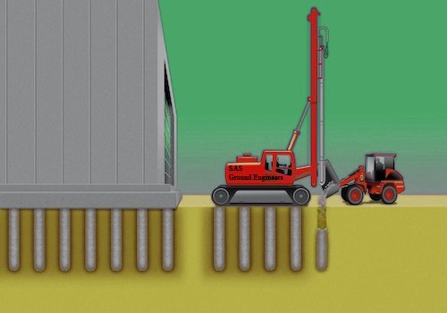
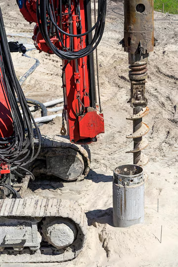
The Tube a Manchette (TAM) grouting method utilizes perforated pipes equipped with specialized sleeve grouts. These pipes are inserted into pre-drilled holes, featuring short rubber sleeves (manchettes) that function as one-way valves, allowing grout to flow in only one direction. To inject the grout, a double packer system is employed, which pumps the grout into the manchette tube until the packer reaches the midpoint of the drilled holes. The application of pressure pushes the grout past the rubber sleeves, causing the sleeves to rupture and allowing the grout to permeate the surrounding soil. TAM tubing is installed similarly to small-diameter PVC pipes used for piezometers or monitoring wells. A sonic or mud rotary drill creates the casing, into which the TAM tubing is placed before the casing is removed. If soil collapses around the tubing, it is acceptable; otherwise, a bentonite slurry is used to fill the annular space.

Applications:

  • Tunnel excavations

  • Cofferdams

  • Cohesion-less granular soils

Permeation grouting, also referred to as cement grouting or pressure grouting, is a technique used to fill cracks and voids in soil and rock, as well as to permeate coarse, granular soils with flowable particulate grouts, creating a solidified mass. This low-pressure injection method enhances the strength and reduces the permeability of granular soils. Portland cement or microfine cement grout is injected under pressure through single or multiple port pipes at strategic locations. It is crucial to match the particle size of the grout with the size of the voids to ensure effective permeation. The resulting grouted mass exhibits increased strength, stiffness, and lower permeability.

Applications:

  • Creating barriers against groundwater flow

  • Underpinning foundations

  • Providing support for excavations

  • Stabilizing and strengthening granular soils

Low mobility (compaction) grouting is a technique that involves injecting low-slump mortar grout to densify loose, granular soils and stabilize subsurface voids or sinkholes. This method is effective for rubble fills, poorly placed fills, collapsible soils, karst conditions, and liquefiable soils. It is often chosen for treatment beneath existing structures since the grout columns do not require direct structural connections to the foundations. The process involves inserting an injection pipe to the desired depth and injecting grout while slowly withdrawing the pipe in lifts, creating overlapping grout bulbs that displace surrounding soils. Sequencing compaction grouting from primary to secondary to tertiary locations enhances its effectiveness, with the high modulus grout columns reinforcing the treatment area.

Applications:

  • Reducing liquefaction potential

  • Correcting settlement

  • increasing bearing capacity

  • stabilizing or mitigating sinkhole risk.

Jet grouting is a technique that utilizes high-velocity fluid jets to create cemented soil structures of various shapes underground. The process involves a grouting monitor attached to a drill stem that is advanced to the desired depth, where high-velocity jets of cement grout (optionally mixed with water and air) are used to erode and blend the existing soil with the grout while rotating and lifting the drill stem. Depending on the application, different systems may be used: a single fluid system (slurry grout), a double fluid system (slurry grout with an air jet), or a triple fluid system (water jet with air-jet and separate grout port). The resulting soilcrete geometry and properties are tailored to the surrounding soil conditions, with erodibility influencing the outcome.

Applications:

  • Underpin foundation

  • Provide excavation support

  • Seal the bottom of planned excavations

  • Manage groundwater

  • Stabilize unstable soils, particularly in areas that are water-bearing.